Showing posts with label All. Show all posts
In recent years the market share of variable geometry turbochargers has been increasing steadily due to the trends of engine downsizing driving development in the field. For more information on these factors which motivate the development of turbocharging technology, see here.

It can be very difficult to find reliable market data without paying thousands of pounds for marketing reports from professional marketing companies. However for the purpose of illustration some data can be obtained freely to describe how variable geometry devices have been taking control of the turbocharging market. The chart below plots the advance of VGT (Also known as VNT, Variable Nozzle Turbocharger) from the early 1990's up until 2010. It can be clearly seen that VNT (VGT) technology makes up a vast section of the diesel market, but only 10% of the gasoline market. This is down to challenges associated with applying variable geometry turbo technology to the high temperature exhaust gases present in gasoline engines, which can be up to 1050 degrees Celsius.


For automotive purposes a big push is underway to downsize engines whilst maintaining vehicle performance; this trend drives the development of automotive turbochargers and VGT in particular. The table below highlights the expected growth in automotive turbochargers in various markets around the world, although figures in USA are constantly being revised upwards due to the introduction of CAFE (Corporate Average Fuel Economy) regulations.


Emissions regulations such as this are the driving force behind turbocharger development and the introduction of additional technologies such as variable geometry and electrically assisted devices. There is considerable variation in regulations around the world and changes in these local regulations have a large impact on the turbocharger sales in those areas. The figures below show the change in regulations with specific details for the european market and upcoming Euro6 regulations, as well as the NEDC (New European Driving Cycle). The Euro6, which will come into power in 2014, brings Europe in line with Japan in terms of NOx emissions and marginally reduces the allowable amounts of particulate matter.

It is also important to note how changes to due to the NEDC will effect how these emissions are measured. The new test contains many transient operations and higher vehicle speeds than previously, this means turbochargers will have to have better performance at low flow rates of exhaust gas. This is the reason for developing VGT devices; variable geometry provides big benefits of regular turbocharging at low loads, and can almost eliminate turbo lag when fully optimised.


Marketing reports can be few and far between for technical areas such as turbocharging, and those that are readily available cost a small fortune, at the time of writing the only readily available reports to individuals will set you back around $2500-5000 for a single user license.

With that in mind we have gathered together as much information as possible from other available sources here in this article, some key references are listed at the bottom of the page.

First and foremost, turbocharging as in industry is on the rise. Global trends in engine downsizing for efficiency gains and reduced emissions are driving the demand for smaller engines, which in turn require turbocharging in order to maintain performance levels. There are a number of options for engine manufacturers to chose from at varying cost, with fixed geometry turbines the simplest and cheapest solution.

Fixed geometry turbochargers have the infamous of problem of slow spooling up, and lack of performance at low RPM ranges. Turbo lag is a commonly used phrase to describe the sensation of very poor transient response from a turbocharger at low engine speeds. A solution to this problem is variable geometry turbocharging (VGT).

The main companies in the Turbocharging and VGT markets are shown in the market breakdown below for various applications:


Great news! Following a few days of tinkering with the experimental setup, we are ready to do some testing on the Holset Turbocharger.


We plan to do 2 types of test:

1) Measuring velocity at the vanes

For this we have to remove the turbine wheel itself and use a pitot tube to measure the velocity at the tip of the vanes in order to draw theoretical velocity triangles to determine turbine performance.

2) Full turbocharger test

For this testing mode we will connect up a custom made oil system for lubrication, along with a calibrated air system for setting the rack position in the VGT. We designed each of these systems ourselves for ease of use when testing. Once setup we plan to measure mass flow, pressure, temperature and turbine shaft rotational speed so that we can determine performance parameters for the compressor side of the turbocharger.


Below is a video of the first time we got the full turbocharger running:


Good news for the new year, testing plans are taking shape, and prototype models have been submitted for 3d printing from ABS plastic. Each part required some modifications for the testing facility, a new post will follow as soon as we have them detailing whats going to happen next! 


Some excellent CAD work here showing the vanes and vane rings of the HY40-V with some dimensions and rendering effects. These models will be used as part of the CFD and FEA models for analysis of the benchmark product:

Holset HY40-V Vane

Holset HY40-V Nozzle Ring

In addition to the internal air volute Minda has begun creation of the cast iron turbine housing. Once completed images will be added below, the current view shows a work in progress:


A big step forward in the modeling stage was made with the completion of the air volume. Mindaugas created this model in Solidworks from technical drawings of the turbine housing and the data from the CMM and FaroArm scans (see the labels on the right for articles on this).

Once imported into ANSYS FLUENT, the vanes will be subtracted using a boolean operation leaving a body of air behind for simulation:

Mindaugas has been busy on Solidworks and has produced some excellent models for use in our simulations, the turbine model is shown here:

Turbine Wheel of the HY-40V Variable Geometry Turbocharger


A few images created from solidworks following the laser scanning process of the turbine housing, the full CAD models will be up soon!

Initial Scan data of the HY40-V turbine housing

Data points from FaroArm scan and CMM machine

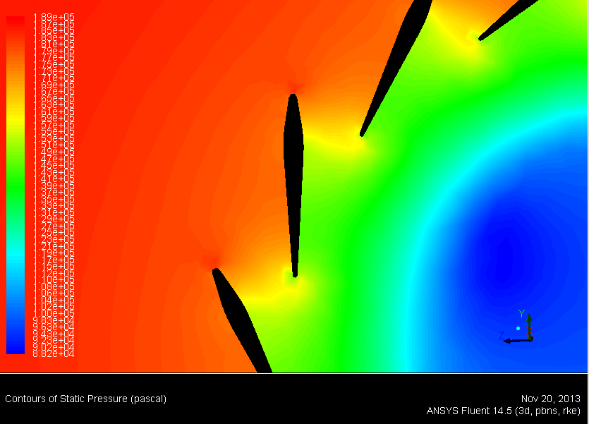
We are setting the benchmark for our own concept designs by running CFD on the original Holset design. This first attempt was run at low load, with the nozzle in the 100% open position.

Ricardo Wave software will be used to find the parameters required for more detailed studies at multiple load conditions.


A new section has been added to the site! A team of engineering students under supervision of the management team have been working towards producing a business case.

Each area will be updated with information relevant to the project, from the market size to how much it costs to hold a patent. The Business presentation will also be uploaded here once produced by the management team, and a shortened version uploaded to YouTube.

TND TV: http://www.youtube.com/channel/UCaZDyw2JSvVUf5zESVTB3ew
As promised we have uploaded the full video of one laser scan process using the FaroArm and GeoMagic software. Please excuse me turning the camera around after 20 seconds or so!

Initial passover of the inside face of the turbine housing

View here or click play on the embedded player below:
http://www.youtube.com/watch?v=W9wtq5b65QI&feature=youtu.be
Please subscribe to our channel!

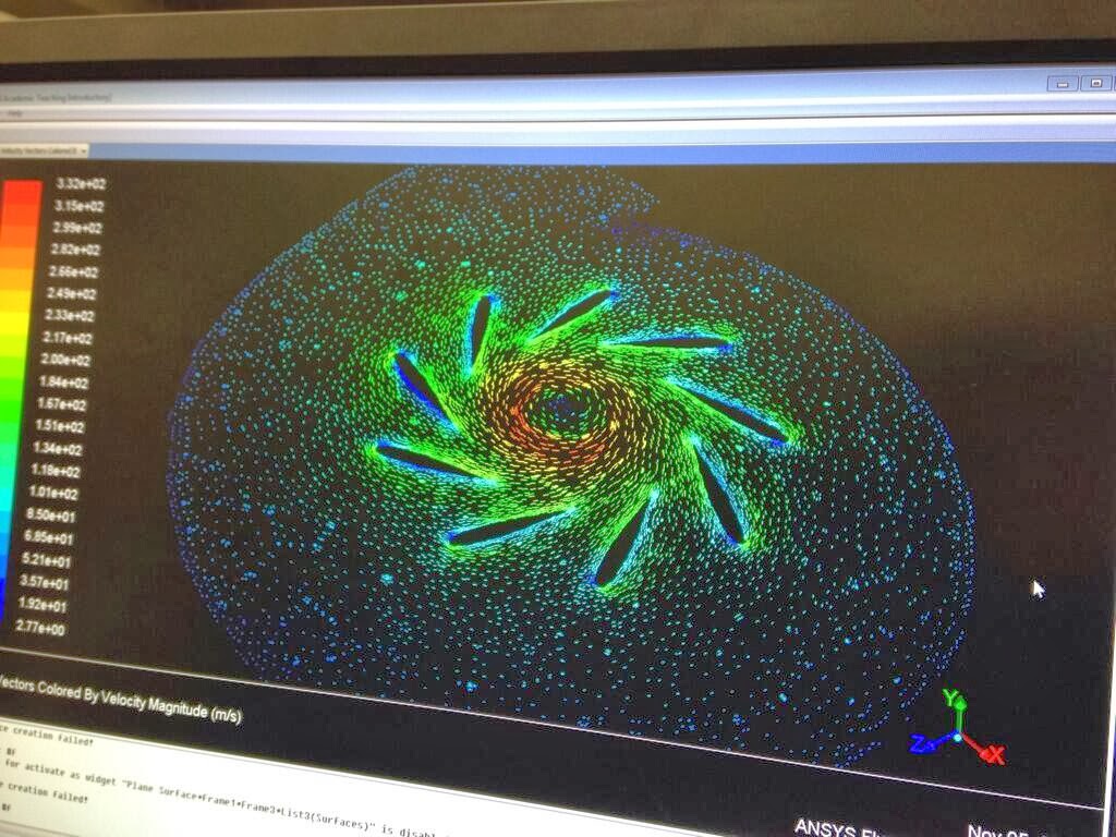
As part of the build up to producing our own component designs, the process has begun of building a numerical model within ANSYS FLUENT for solving. Using borrowed CAD files of a similar turbocharger, I experimented with boundary conditions and solver settings; although the mesh used was very coarse.

Solver: K-Epsilon with SST (Shear Stress Transport Equation)
Mesh Size: Approx 200,000
Inlet Velocity: 70m/s
Inlet Temp: 1030K

Basic Solution with coarse mesh: Velocity Vectors through a plane

The central area was left free here (ie. No Rotor defined) for simplicity, I plan to work on a number of different models and decide on the best for analysing our designs.

Todays work involved the scanning of some 3D components using a FaroArm (See here: Faro.com). This equipment uses laser technology to determine a 3D profile and produce a 'mesh' of the part. The file opens in a software called GeoMagic which can be used to edit the data points and reduce the file size before exporting into more common CAD formats.

FaroArm and Components to be Modelled

A FaroArm is essentially a portable CMM (Coordinate Measuring Machine) that can use either a ball probe or a laser probe for mapping 3D parts. With the help of a Keith, a Brunel Technician, we set to work scanning the outside of the turbine house shown below and the turbine wheel.

1 Side of the Turbine Housing Scan in GeoMagic

GeoMagic automatically relays the data onto the screen and then produces a mesh as shown above. Initially our scan contained around 3 million nodes (data points) but following a series of reductions using the "decimate" tool the final file contained 300,000 nodes and was approximately 100MB. The file produced is in a .stl format which can then be opened in Solidworks for modelling purposes.

The turbine housing was successfully completed, however the turbine will be scanned after arm calibration in a weeks time. A video will follow shortly!


The first major step forward in our project occurred with the delivery of our Turbocharger. The model in question is a Holset HY40-V with a sliding vane mechanism. The guys were very keen to get this taken apart, and we were quick to grab a copy of the manual and technical drawings so we could start work...

A collection of the dismantled turbocharger parts following an hours work. 

Thanks to Vijay, our resident techno-wiz, we also have a time-lapse-style video of some of the dismantling process, which can be seen below (Or on youtube: http://www.youtube.com/watch?v=HV8WkWoLCdw):


All in all this was a rewarding hour or so to spend, we all developed a better understanding of how the product goes together, this can only help us in trying to improve its design. The next steps in the process of initial analysis are to scan significant parts using either a CMM (Co-ordinate Measuring Machine) or a FaroArm laser scanning tool.

These steps are to enable us to build an accurate CAD model by importing physical data from the scanning machines; from this point we can use the initial design as a benchmark in CFD and create our own designs to hopefully improve performance.


Welcome to the webpage for Turbocharger Nozzle Development.

We are a student team based at Brunel University, London, embarking on a project to redesign the nozzle of a Variable Geometry Turbocharger (VGT).

The site will be updated with content shortly so please be sure to come back and check out how we are getting along!

© 2013 Turbo Nozzle Development is designed by Templateify & Sponsored By Your Link Here